How does a CNC press brake work?
A CNC press brakeis a modern machine for sheet metal bending. Modern press brakes are operated and...

Choosing a press brake can seem daunting at first, but it really boils down to understanding the kind of work you'll be doing and matching the machine's capabilities to your needs. Here are some key questions to ask yoursefl: what's the longest piece of material you'll need to bend? How thick will the material be? The bending length and material thickness will determine the tonnage (bending force) and throat depth (clearance between the frame and ram) that you need in a press brake.
The length of the press brake depends on the maximum length of the part to work. If bent per stations, it is useful to consider the purchase of a longer press brake, which allows multiple stations to be implemented. For example, for a sheet measuring 1100 x 700 mm, you are advised to choose a press brake measuring 2000 mm long.
It is intended as the bending force of the machine. In other words, it refers to the capacity to bend of the press brake. Tonnage depends on various factors, first of all the material: a ductile part requires less bending force; on the contrary, a more resistant material such as stainless steel or high strength steel requires greater force.
Our online press brake tonnage calculator is your ideal tool for accurately determining bend parameters for your sheet metal. In just a few simple steps, you'll get detailed information on:
Tonnage: The force required to perform the bend.
Inside radius: The inner curvature of the bend.
Minimum flange length: The shortest possible length of the flange to prevent breakage.

You should always oversize the press brake capacity by around 20 – 30% with respect to your data in order to allow for the variability in the characteristics of the metal and so that you are not in danger of working to the limits of the machine’s capacity.
One of the most common misjudgements is to confuse the total force needed to bend a given sheet metal part with the tons per metre for the specific thickness, material and die. Find out more in this guide.
Clearance is simply the front opening of the press brake. A press brake with a larger stroke is a machine equipped with greater intermediates that allow easier extraction of the bent parts.
Different metals have varying properties and behave differently when subjected to bending. For instance, aluminum is generally more malleable than stainless steel. Understanding the characteristics of the specific material you’re working with is essential in determining the appropriate press brake and bending parameters.
Our Ultimate Guide to Sheet Metal Materials provides expert insights and practical advice. Explore now to choose the perfect material for your project.
Complex press brakes offer advanced features and automation, but they often require skilled operators. If your team lacks the necessary expertise, consider the time and resources needed for training. Weigh the benefits of increased capabilities against the potential challenges of operator training and maintenance.
There are many different types of press brake machines. Each of these comes with its own set of advantages and limitations. You can choose the right press brake based on your use case. These different types of press brakes are:
Mechanical press brakes: These are the most basic type of press brake and are generally the most affordable. However, they are also the least versatile and can be difficult to operate precisely.
Hydraulic press brakes: These are the most common type of press brake and offer a good balance of power, precision, and versatility. They use hydraulics to power the ram, which allows for more precise control over the bending force.
Pneumatic press brakes: These are a good option for lighter-duty bending applications. They are quieter and faster than hydraulic press brakes, but they also have less bending force.
Servo press brakes: These are the most precise type of press brake and are a good option for high-precision bending applications. They use servo motors to power the ram, which allows for very precise control over the bending position and force.
CNC press brakes: These press brakes are computer-controlled and can automate many of the bending tasks. They are a good option for high-volume production runs or for complex bending jobs.
Hybrid press brakes: These combine the power of hydraulics with the precision of electric motors. They are a good option for applications that require both high precision and high bending force.
Tandem press brake: particular configuration that involves the connection of two machines into one, but there are also solutions that combine three bending machines (tridem) or 4 bending machines (quadrem). Read our guide on "What to know before choosing a tandem press brake".
Intermediates are adaptors to insert between the beam and the punches and are very useful because they allow deep box structures to be easily made.
The tool clumping systems are sub-divided into:
manual locks;
semi-automatic locks:
pneumatic blocks;
hydraulic locks;
The choice of correct locking is fundamental to reduce the work times and correctly manage the work zone.
It is a manual semi-automatic lock with rapid front locking-unlocking system of the punch. Operation is very simple and, compared to the traditional manual solution, allows faster and easier re-equipment of the machine.
In fact, by moving the locking lever, the punch is released to remove it from the front; while, on closure, the punch is automatically brought to stop and perfectly aligned.
The automatic tool locking systems allow equipping of the press brake in complete safety. The tools are automatically aligned, positioned and fastened. This solution drastically reduces the equipping time and considerably increases production.
Today, a modern and innovative solution exist that allows automated change of the punches and matrixes. For example, VICLA hybrid press brakes can be connected to an automatic tools warehouse that allows equipping, even on multiple stations, of higher and lower tools.
This system is customisable and designed to measure according to client requirements; it reduces setup by 4 or 5 times compared to manual tasks and automatically performs even the most complex equipping, managing 70 mm wide V matrices, rod holding tools and allowing the tool to rotate 180°.
Automation covers everything, including upstream operations. One of the more interesting aspects is programming by the technical office: the CAD/CAM system processes the three-dimensional file, creates the best bending cycle and sends the program to the machine that is automatically equipped, referencing the bending sequence directly on the numerical control. All tooling and machining data are automatically saved at the end of the work and exported to management for a 4.0 key data analysis.
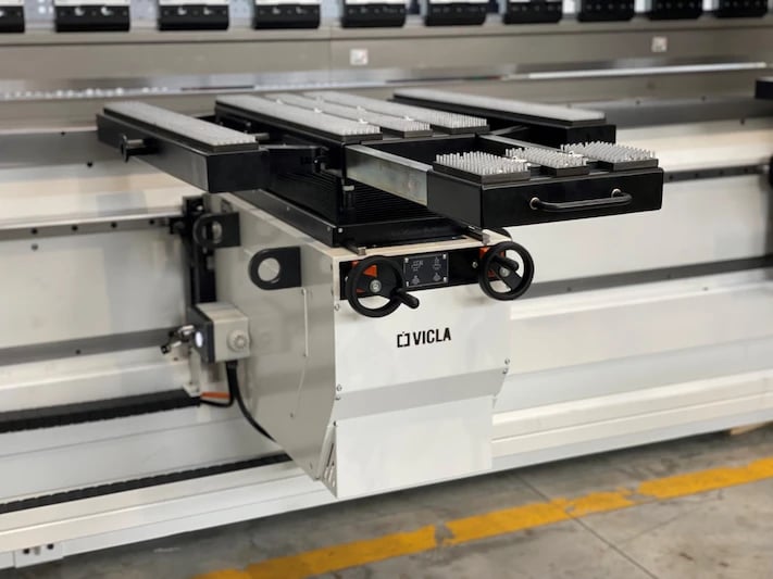
The rear gauge is a motorised structure on which the references are set and can be moved and positioned to allow a variety of complex bends.
Movement of the back gauge along the depth of the machine is called axis X. Vertical lifting is called axis R.
 It consists of very important and useful tools to support thin sheets. They are equipped with pneumatic operation and a Teflon coating that prevents marks on the material. They can also be activated by numerical control. There are 2 references and they are usually manual, but they can be automated and controlled directly by the CNC; the positioning of the stops is along the Z axis.
All towers are equipped on VICLA press brakes with a visual LED stop. Switch on of the LED ensures contact of the sheet with the reference.
In more accessorised versions, the towers are:
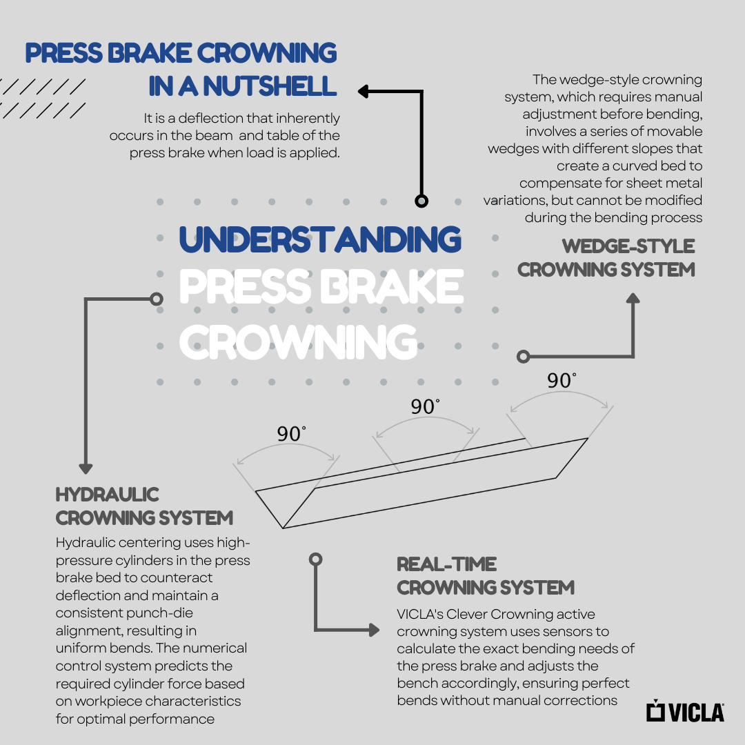
The greater the length of a bending machine, the more the problems relating to the structural failure of the bench, making it more difficult to get a well worked part. Over the years, technological evolution has taken giant steps, passing from manual systems (such as using paper shims under the matrix) to automatic, mechanical or hydraulic systems, where a pre-load of the assumed deformation was determined. The limit of these systems is based on a theoretical calculation set by numerical control.
VICLA has developed an intelligent system that improves the work in the workshop: the active Clever Crowning system.
Thanks to special sensors in the beams, crowning enables measurement and compensates deformations in real time. There is no need to set any data; the system actively reacts to changes in characteristics.
Each press brake, despite its robustness, is subject to structural bending, during the bending phase, and obviously the deformations are much bigger the greater the effort the machine has to make.
The main deformation is crowning, which corresponds to bending of the beam which is pushed into position by the side cylinders; the other (and for many reasons semi-unknown), is called in jargon “yawn” and is the tendency of the frames to open in the throat zone.
Thanks to the Flex system the sheet metal press brake dynamically compensates any deformations based on the effort required: the CNC receives the data from the pressure sensors of the cylinders, which are interpolated in real time to establish the correction to implement.
It is not enough to just add an inverter to call a press brake "hybrid"; in fact, technological innovation revolves around a specific hydraulic system, which in the case of the standard hybrid model, includes a completely independent dual hydraulic circuit, each equipped with its own tank, motor, pump and inverter.
The functional separation of the two cylinders allows optimised control according to the load required for each cylinder; moreover, it allows efficiency to be achieved in terms of energy.
It is a system able to minimise wear of the machine by concentrating all its efficiency and automatically balancing the working pressure exclusively on the side that is used during bending of that specific part.
A further level of performance is provided by the Hybrid Plus model: the system consists of a brushless motor for each cylinder, capable of providing high forces and high movement speeds. It is an even more compact system consisting of a direct drive motor and pump, installed directly on the cylinders. with significantly reduced piping.
The results in numbers of this technological innovation are significant, as seen on the graph.
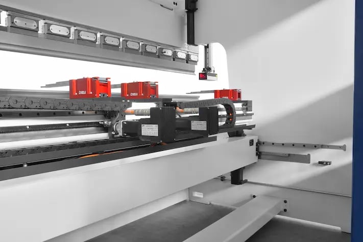
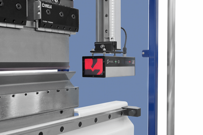
V-Control consists of two laser sensors mounted on linear guides that slide to the rear and front of the press brake bench taking the measurement in one or three points depending on the length of the piece. Located on the sides of the matrixes, they have the purpose of reading, through a system of lasers and cameras, the inclination of the edges of the bends during deformation.
It is the most complete and performing solution for automatic angle measurement and control.
Angle reading takes place in 3 phases:
A laser beam is projected on the sheet metal surface
The camera detects the elastic recovery of the material
The CNC automatically sets the correction suitable to obtain the system desired angle that we use on our VICLA press brakes and is the best you can find on the market. The guaranteed precision is very high and in the order of fractions of a degree.
The system is also able to historicize the elastic recovery of the sheets, ensuring a constant and specific self-learning of the press based on the real situation of the company. Obviously the angle control system guarantees the best performance if it is supported by solid and precise mechanics and perfect integration with numerical control.
With the latter, there is a continuous data exchange dialogue that allows perfect application with each item being processed. If, for example, for volume issues, a specific bend cannot be measured by the angle control system, it can be "linked" to the previous reading made on another flap of the same piece.
Vicla angle control is a safe investment and surprisingly quick return as it makes continuous measurement operations by the operator completely unnecessary with an exponential increase in productivity and quality.
There are essentially three types: inserts in the punch, hosted in the matrixes or applied to parallel sliding trolleys the exact same as those of the optical systems and placed on the sides of the bench.
On first examination, it could appear a definitive solution, however these are also not without limitations which, in practice, only appear during their real use.
The first is without doubt the installation difficulty. This is the typical limit of the controls inserted in the tools that include use of special punches and matrixes equipped with sophisticated, sensor-based strips.
Such angle control systems have very poor versatility when you consider they are not usable by changing tool set-ups.
Another limitation is their characteristic fragility.
Being small and very sophisticated mechanical elements, they are easily subject to failure caused by accidental impacts or malfunctions due to the accumulation of dust and dirt.
Optical control is directly assembled on photocells to capture images of the profile detecting, calculating and correcting the bending angle.
One of the most sophisticated optical controls is the IRIS PLUS system. Although it is part of the optical angle control unit, IRIS plus is an alternative solution because it can perform an extremely accurate reading during the bending phase while remaining at a safe distance from the work area.
This eliminates any interference between the parts and the angle control devices and achieves totally versatile use.
The system, in fact, allows very interesting accuracy and reliability if the emitter and the receiver are not beyond a certain distance.
After approximately 2.5 metres, in fact, there is a natural increase in the phenomenon of refraction of light rays that reach the control system which are not sufficiently clear. The "noise" can be reduced by decreasing the sensitivity of the system but with the consequence of not ensuring the same accuracy in the reading of the bend.
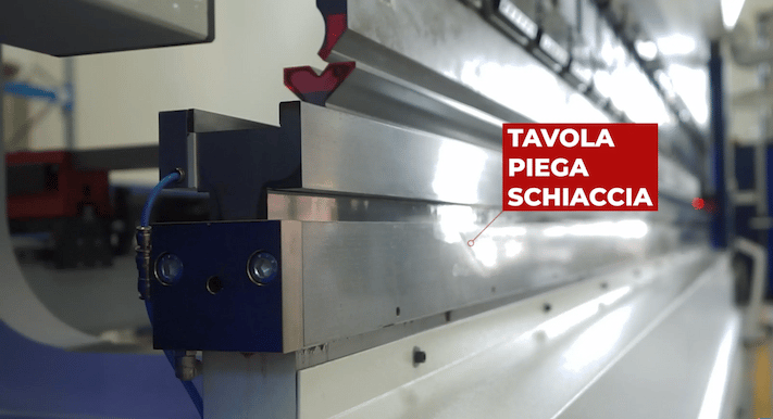
The bottom bed has a bending/flattening table in order to perform flat hem bends without the need for a dedicated die. Its versatility makes it the ideal solution for companies that carry out many flat hem bends. The option is built directly into the die holder, and therefore can be used in conjunction with any other die that has a standard connection without the need to disassemble the table.
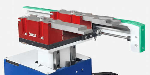
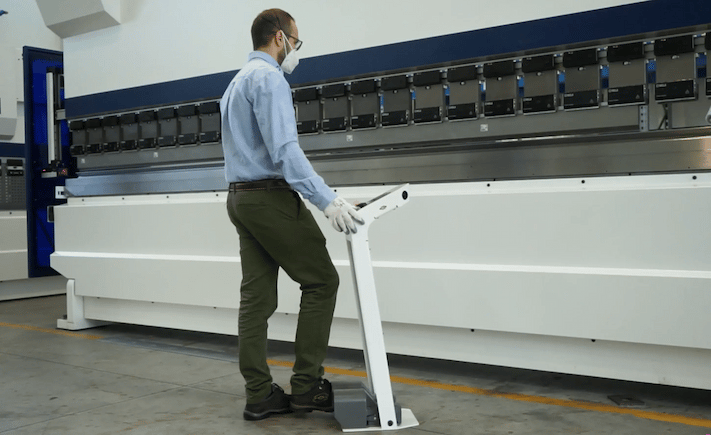
These front supports have a linear guide that extends beyond the bottom beam. Their height can be adjusted and they also slide sideways and rotate. A practical clamp-release system makes them very easy to mount and remove quickly.
They can lift weights up to 380kg. Use of the metal sheet bending followers offers an important advantage to reduce risks for the operator and increase the quality of the bent parts: it was designed to avoid counter-bend effects and reduce the need for other operators. It can also be easily removed from the front and placed on another bending machine.
An extension of the linear guides, extending beyond the bench. This solution is used to park the sheet metal supports when not in use.
It is powered by an integrated solar panel that allows you to get up to 20% more autonomy from battery life; it does not require connection, nor cable laying. The ultrasonic sensors are located on either side of the lower bench to transmit and receive data wirelessly.
The system indicates via the incorporated LED the right locking position of the equipment during tool configuration and indicates the position of the active tool in production mode.
It is a real and proper visual aid immediately available to the operator who, by doing so, does not waste time measuring and understanding where to position the tool and can dedicate his time to other operations.
A CNC press brakeis a modern machine for sheet metal bending. Modern press brakes are operated and...
Hydraulic press brakes, known for their precision and power, utilize oil cylinders to control the...
Press brakes are essential tools in metal fabrication, but neglecting their maintenance can have...